

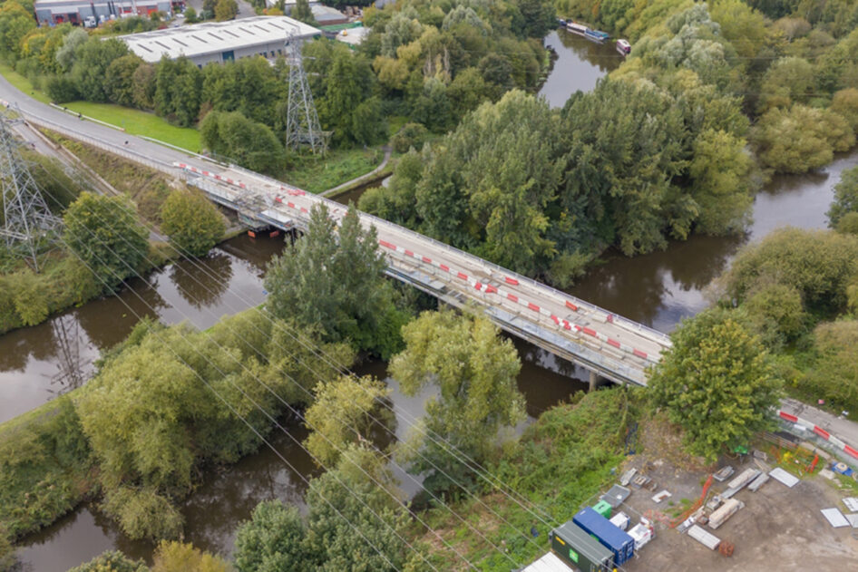
Skelton Grange Bridge, Leeds
Main image credit: Volker Laser
The problem
In December 2023, Volker Laser and Buro Happold asked us to survey the location and trajectory of 626 drilled holes in the superstructure of Skelton Grange Bridge in Leeds, with the data required to support the design of new strengthening works.
The challenge was to capture both the position and alignment of the holes – typically 40mm in diameter and between 400mm and 1100mm deep – accurately enough for fabricated reinforcing steel to be designed, manufactured and installed without site adjustment.
Research phase
As Chartered land surveyors, M J Rees and Company Limited has supported engineering survey projects since 1972, but this brief required a method beyond standard site measurement techniques.
The first requirement was to define the intersection of each hole with the bridge face; the second was to determine the trajectory of each hole efficiently enough for both site capture and office processing.
Conventional total station, scanner, pole and prism approaches could provide elements of the answer, but they would not deliver the required efficiency across 626 individual holes.
We therefore needed a repeatable survey methodology that would reduce time on site, streamline office processing and provide sufficient confidence for fabrication.
The solution
We adapted a trajectory-mapping technique used in crime scene investigation and ballistics, applying it to a civil engineering survey challenge.
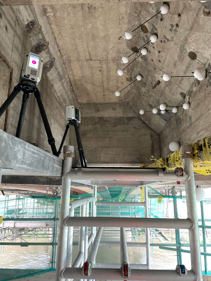
To minimise the number of scanner setups and ensure visibility of all spheres in the resultant point cloud we employed two scanners simultaneously, observing from different viewpoints. This also introduced useful redundancy for checking and validating the results.
By laser scanning two spheres mounted on a rod inserted through each drilled hole, we could derive the hole trajectory in the same way that ballistics analysis can establish a bullet path.
The results
A typical setup with two Leica RTC laser scanners and the Koppa trajectory spheres mounted on carbon fibre rods can be seen in the image below:
From the registered point cloud, we modelled the sphere positions and derived the location and trajectory of each drilled hole.
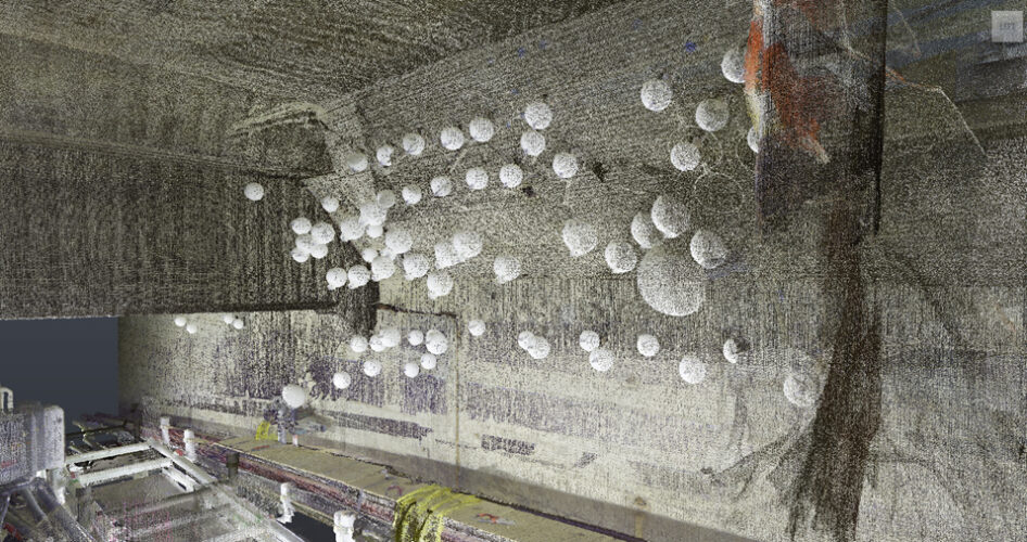
We created two coordinated models: one showing the surveyed holes and one showing the surveyed bridge structure.
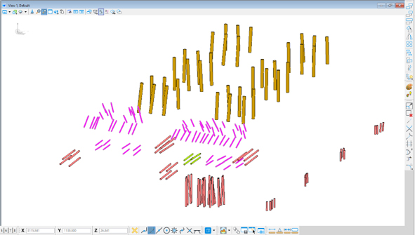
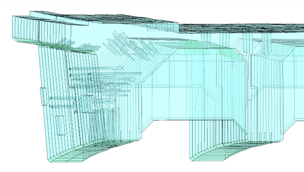
The AutoCAD model was supplied to the client and imported into Tekla to support the detailed modelling of the steel reinforcing.
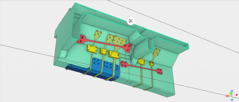
The model was then issued to the fabricators, who used CNC machinery to cut and fold the parts ready for installation on site.
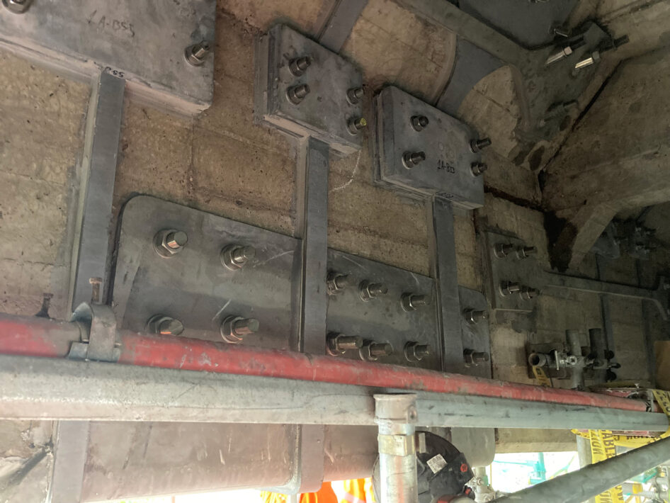
The outcome was decisive: there was no on-site manipulation or reworking, all holes lined up within tolerance, and the grout quantity matched the calculated volume.
The project was subsequently shortlisted for the NSE Projects Team of the Year 2025 reflecting the strength of the technical approach and the quality of the delivery.
Find out more about the work carried out here.
Conclusions
- Early collaboration at specification stage is vital to define the required quality, accuracy and usability of survey deliverables.
- Time invested in scheme design and method development reduces delivery risk on complex engineering surveys.
Comment from the client’s structural engineer at Buro Happold:
“Thanks again for your input there – we couldn’t have done it without you”
For more information contact Robert Brassington or Sarah Hurley.
Tel 01454 252930
Email survey@mjrees.co.uk